 |
Installation for SPIKE
2 Flamin' Frames
| ||||||||||||||||||||
|
PLEASE READ THESE INSTRUCTIONS. They are set up with the power connection first. Then some general tips for these light kits. Followed by the instructions for installing the light frames and finally the various electronic connections. |
|
IMPORTANT! These SPIKE 2 Speaker Light Kits use +5VDC, high current light strips. They are not compatible with aftermarket accessory power supplies and are not meant to hook into a game's circuit boards. This SPIKE 2 Speaker Light Kit includes its own power transformer, which automatically switches on and off with the game's power. |
|
This is a high-power mod that uses 100VAC - 240VAC. Please follow the install instructions and be sure to UNPLUG YOUR GAME before doing anything else. |
|
THE POWER CONNECTION FOR THIS TYPE OF LIGHT KIT IS IN THE BACKBOX. IT IS NOT INSIDE THE CABINET OF THE GAME. THERE IS NO REASON TO LIFT THE PLAYFIELD OR EVEN OPEN THE COIN DOOR WHEN INSTALLING THIS TYPE OF LIGHT KIT. |
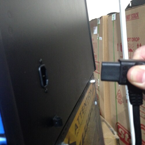
| On these SPIKE 2 Speaker Light Kits, the power connections are different from one
another depending on if you have a North America game or an international game. The
international games do not include a high-power Bill Validator connection like the North
America games, so they have to get their power directly from the game's power switch. You will
only receive one AC power cable with each Deluxe SPIKE 2 Speaker Light Kit purchased. Orders
placed from the US and Canada will receive the North America power cable and all other
countries will receive the international power cable. If you need a power cable from a
different region than where you are ordering from, please contact me at my support e-mail before placing your order to explain the
situation. In both cases, the Speaker Light Kit is still automatically switched on and off when
the game switch is turned on or off. You can find the... NORTH AMERICA POWER CONNECTION INSTRUCTIONS HERE. and the INTERNATIONAL POWER CONNECTION INSTRUCTIONS HERE. Then come back here for some tips before the light frame installation. |
|
Here are some tips and things to know
before beginning the light frame install: |
|
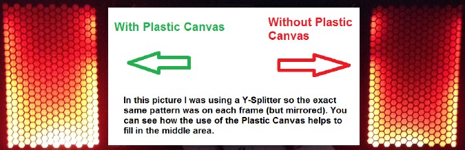
On the left side, you can see what the typical LE type install would look like without the
foam. On the right side is the same speaker setup with the speaker foam (and plastic canvas)
installed. You see much more of the flame effect with the foam (and plastic canvas) in place. I
do sell the speaker foam, but it should have been included with all pro and premium SPIKE 2
games (and some LE games). The left side with the 5.25" speaker showing looks fine, but I
prefer the right. This is just a judgment call on which you prefer and how you like things. |
|
As far as my recommendations go, the top of the list is makeing sure you are using the speaker foam if you are using the factory 4" speaker plates. No one wants to see those off-center speaker holes with the stupid looking bars running through them. If you are determined to not use the foam AND use 4" speakers.....buy a set of my 4" SPIKE 2 speaker plates. At least they center the 4" speaker hole in the middle of the grill area and have the crappy looking bars removed from the speaker holes. They are available on the accessories page. |
|
Here are some other things you should be aware of before moving on to the frame
installation: |
|
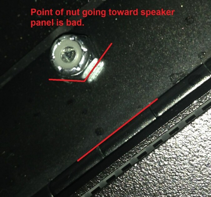
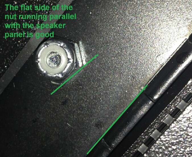
Make sure the speaker panel is pushed in toward the backbox when you are tightening down the bottom hex posts. This is also mentioned in the frame install PDF as it is very important when it comes to ensuring the speaker panel will close as smoothly as possible after the installation. |
|
Be mindful when putting down the magnet-backed light strips on the frame after you have put in the screws to hold the LCD screen in place. There are gaps in the magnets where the screw heads should go. It may help to put a slight bend between the 2 bulbs where the screw heads will land. No matter what is done, the screw heads will bump the light strip out a bit, but with some care, you can make sure the magnets on both sides of the screws are down against the light frames instead of ramping off of them and causing a bigger gap than is needed. A little bit of care when putting the magnets down on the frames may prevent having to remove the speaker plates and tap them down again to have them look as they should. |

|
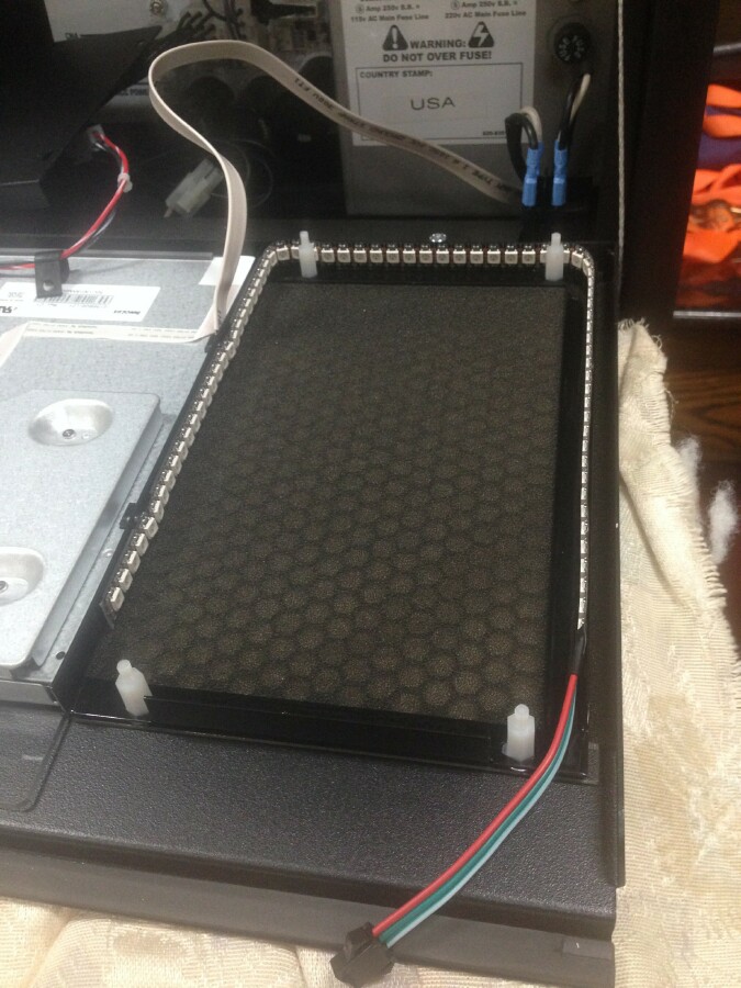
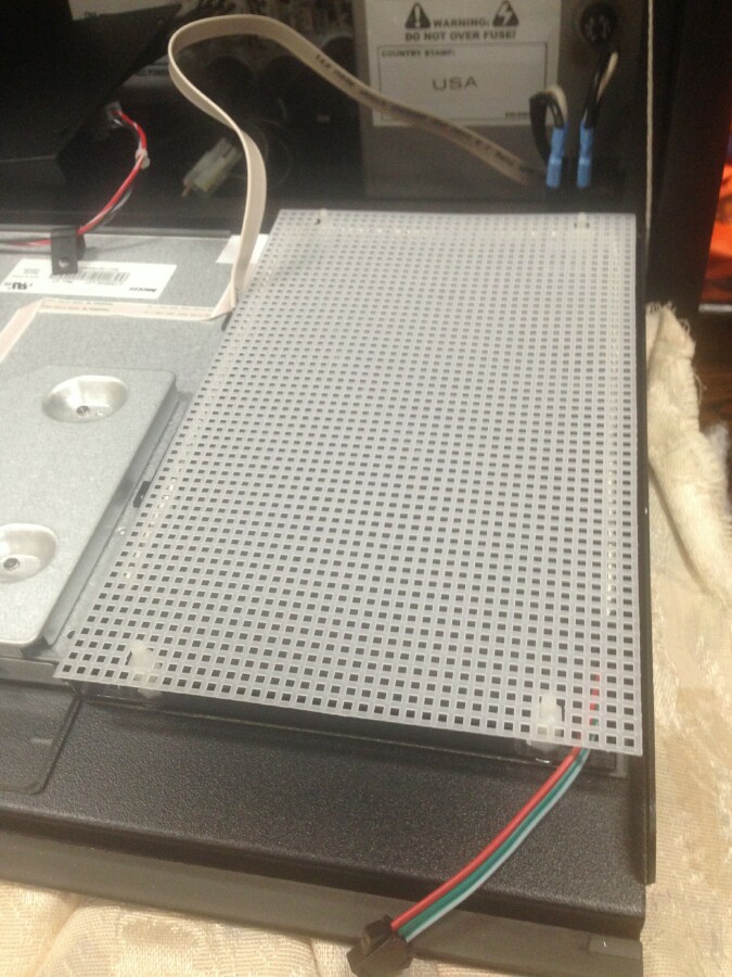
If the plastic canvas is used with the foam, as recommended, I suggest you mount it on top of the hex posts after the light frames are in place. With the plastic canvas in the rear of the lit area, it does just as good of a job at spreading the light as it would directly behind the foam, but its grid pattern is less visible in the back. |
|
If you have speakers that have tweeters that protrude out and are pressing into
the plastic canvas when it is mounted in the rear or are having speaker foam sagging issues
(which has never been a reported issue), you can mount the plastic canvas directly behind the
speaker foam. |
|
I would also like to mention, there is no need to tighten the nuts to hold the speaker
plates on to any real degree. It IS important to get the hex posts down firmly. Especially on
the bottom where they are holding the speaker panel hinges in place. Having said that, there is
no reason to go extreme on that either. Get the posts down tight, but do not over-tighten
them. |
|
For the last of the tips, I would like to explain something that may or may not need to be
done, but in any case, it's best to check and see how your game looks. After any type 11, 12 or
14 SPIKE 2 Speaker Light Kit install you may notice the speaker panel being a bit stiffer to
close. This is pretty normal, but it does vary from game to game and can be made worse or
better by various factors. |
|
This is not a Flamin Frames specific issue. It is something that has always been there with some games and the introduction of the plastic canvas and Stern changing from Keps nuts to thicker nylon insert nuts has made it more noticeable. As it is, it's just the way it is. It's not an issue and if the light kit is installed correctly and the nuts adjusted as suggested your panel will close fine, just with a bit more closing pressure needed. |
|
THOSE WERE THE CLIFF'S NOTES TIPS. Now please follow the light frame
installation guide at the link below THEN COME BACK HERE for the other electronic
connections. |
|
Here are the other electronic connections that you will have to make. The included Y-Splitter is ONLY used if you want to use one of the two controllers' output wires. This would give a more symmetrical look as it would then have the same flaming patterns on both frames (but mirrored). |
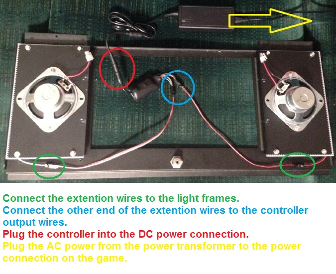
| The rest of the connections are pretty straightforward and clearly shown and
described in the picture above. The NORTH AMERICA power connection instuctions are HERE. and The INTERNATIONAL power connection instructions are HERE. I will add a suggestion, to place the included power transformer on the floor of the backbox with it slid as far forward toward the back of the LCD screen as it can go. This should make it so that if the head is folded down, the power transformer doesn't have any room to shift forward. Then if the game is being wrapped or strapped and stood up to move, the power transformer is back to sitting on the backbox floor in its natural position. There is also enough cable length to put the power transformer in the bottom of the cabinet if one would choose to, but I like the idea of keeping everything in the back box so fewer cables run between the backbox and cabinet. 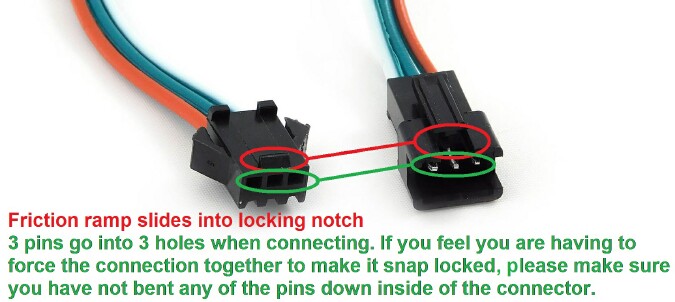 Other simple things to mention are, the connections to the light strips, extension cables and controller are made so they can only be plugged in the correct direction. When you give them a look you can see how they snap together. There is a small friction ramp that slides into a notch on the top of the other connector. When these are connected, the 3 pins in one side are meant to slide into the 3 holes on the other. If you feel you have to use much force to get these connections to lock together, please make sure you have not bent any of the pins down inside of the connector. The power transformer is non polarized so it does not matter how the AC power cable is plugged into it. After everything is mounted and connected you will now need to attach the support cables back to the speaker panel. Get some help or find something to support the speaker panel as you attach the support cables, washers and nuts to the top inner nylon studs. Again, make sure the nuts are threading on straight and you DO NOT OVER-TIGHTEN THEM. Also, make sure the support cables are positioned toward the backbox when they are tightened so that when the speaker panel is folded down, it is supported by the cables in a natural position. Then put the translite back in place, close and lock the speaker panel, plug the game back in and turn it on. The Flamin' Frames kit should come on and "ignite" in a few seconds. Enjoy. If you have any questions or issues, feel free to contact me at my support e-mail. |
Back to Manuals or Back to Type 14 Speaker Light Kits
|
© Copyright SpeakerLightKits.com, 2026. All Rights Reserved.