Installation for Deluxe
5.25" SPIKE 2 Speaker Light Kits (Type 13)
|
IMPORTANT! The Deluxe SPIKE 2 Speaker Light Kits use
+5VDC, high current light strips. These kits are not compatible and do
not share any electronics with other types of Speaker Light Kits. They are not
compatible with after market accessory power supplies and are not
meant to hook into a game's circuit boards. The Deluxe SPIKE 2 Speaker Light Kit includes its
own power transformer, which automatically switches on and off with the game's
power.
|
|
This is a high power mod that uses 100VAC - 240VAC. Please follow the install
instructions and be sure to UNPLUG YOUR GAME before doing anything
else.
|
|
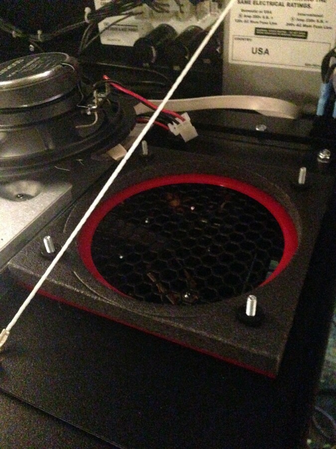
THE POWER CONNECTION FOR THIS TYPE OF LIGHT KIT IS
IN THE BACKBOX. IT IS NOT INSIDE THE CABINET OF THE GAME. THERE IS NO REASON TO LIFT THE PLAYFIELD OR EVEN OPEN THE COIN
DOOR WHEN INSTALLING THIS TYPE OF LIGHT KIT.
|
|
On the Deluxe SPIKE 2 Speaker Light Kits, the power connections are different from one
another depending on if you have a North America game or an international game. The
international games do not include a high power Bill Validator connection like the North
America games, so they have to get their power directly from the games power switch. You will
only receive one AC power cable with each Deluxe SPIKE 2 Speaker Light Kit purchased. Orders
placed from the US and Canada will receive the North America power cable and all other
countries will receive the international power cable. If you need a power cable from a
different region than where you are ordering from, please contact me at my support e-mail before placing your order to explain the situation. In
both cases, the Speaker Light Kit is still automatically switched on and off when the game
switch is turned on or off. You can find the...
NORTH AMERICA POWER CONNECTION
INSTRUCTIONS HERE.
and the
INTERNATIONAL POWER CONNECTION
INSTRUCTIONS HERE.
Then come back here for a description of the light ring mounting and the rest of the
electronic connections.
|
|
The physical mounting of the light rings in this kit is very simple. With the game already
turned off, unplugged, the translite / backglass removed and the speaker panel folded
down...
|
|
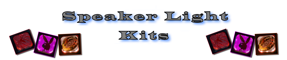
You will need a 5/16 nut driver to remove the nuts holding the speaker on.
|
|
Take off the nuts and remove the speaker.
|
|
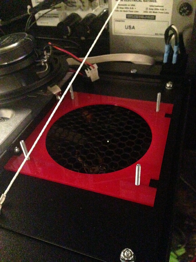
Now remove the 4 nylon spacers and the speaker gasket. If you are removing, adding or
switching a speaker surround...now is the time to do that. Keep in mind, a speaker surround
does not need to be used at all and I have found that ones that do allow light to shine through
them look best with the light kits.
|
|
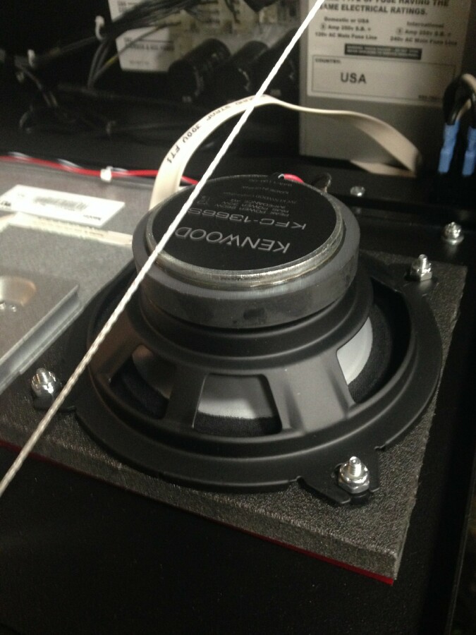
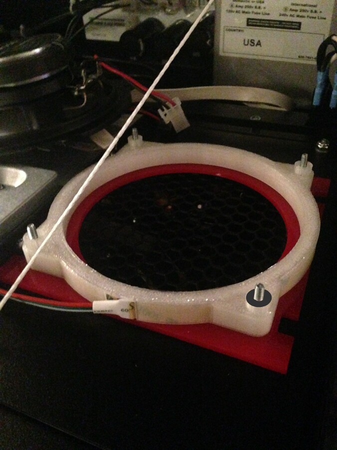
Now it is time to put the light ring in place. The ring should be placed with the open light
strip channel down (toward the speaker panel) with the speaker mounting nubs at the mounting
holes facing up.
As for how the rings should be positioned on the mounting posts, I recommend that
the opening, where the light strip is going into the ring, be placed up (toward the top of
the speaker panel when it is closed). You will also notice that one of the light rings has a
mounting nub that is colored black. I suggest this to be the ring for the right side and that
black nub be the one toward the top of the speaker panel (as pictured).
Keep in mind, these are just suggestions and mounting the ring with the light strip
opening in another position or the rings on different sides are fine. I recommend them to
be placed this way as it has the light strips going into the rings in a natural position and
also has the light rings displaying a symmetrical light show with each other.
Carefully slide the light ring onto all 4 threaded mounting posts evenly and
make sure it is down all the way.
|
|
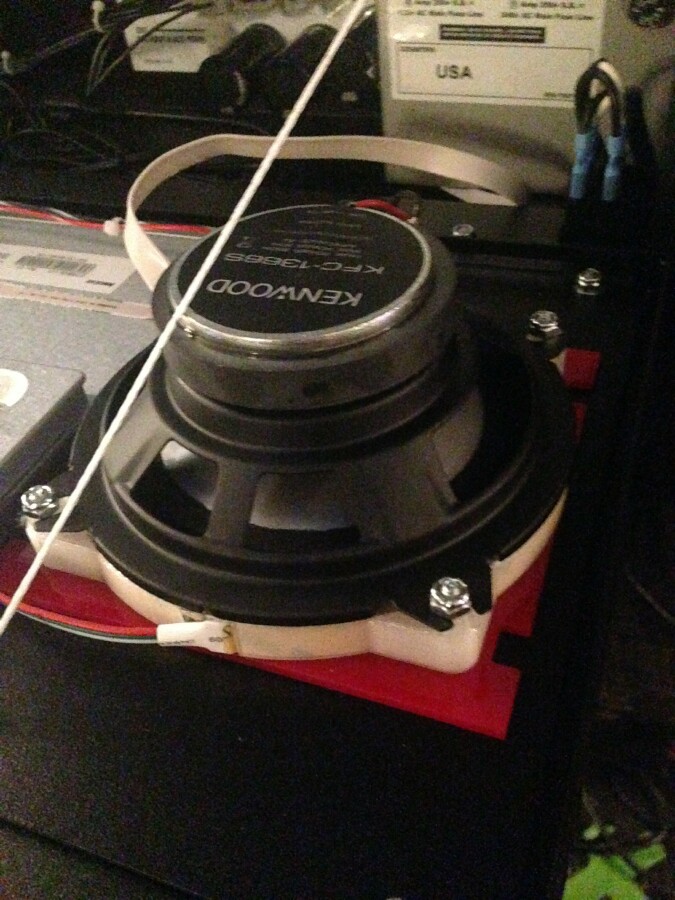
Now it is time to put the speaker back on. Secure it with the nuts and do not overtighten
them.
|
|
When you have both of the light rings mounted and the speakers back in place...it is now
time to move on to the other electronic connections on the light kit.
|
|
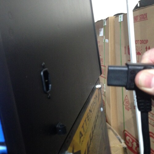
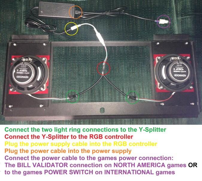
The rest of the connection are pretty straight forward and clearly shown and described in
the picture above.
The NORTH AMERICA power connection
instuctions are HERE.
and
The INTERNATIONAL power connection
instuctions are HERE.
I will add a suggestion, to place the included power transformer on the floor of the
backbox with it slid as far forward, toward the back of the LCD screen as it can go. This
should make it so if the head is folded down, the power transformer doesn't have
any room to shift forward. Then if the game is being wrapped / strapped and stood
up to move, the power transformer is back to sitting on the backbox floor in its
natural position. There is also enough cable length to put the power transformer in
the bottom of the cabinet if one would choose to, but I like the idea of keeping everything in
the back box so there are fewer cables running between the backbox and cabinet.
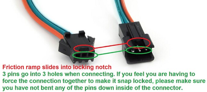
Other simple things to mention are, the connections to the Y-Splitter are made so they can only
be plugged in the correct direction. When you give them a look you can see how they snap
together. There is a small friction ramp that slides into a notch on the
top of the other connector. When these are connected together, the 3 pins in one side are meant
to slide into the 3 holes on the other. If you feel you have to use much force to get these
connections to lock together, please make sure you have not bent any of the pins down inside of
the connector.
The power transformer is non polarized so it does not matter how the AC power cable is
plugged into it.
Then put the translite / backglass back in place, close and lock the speaker panel, plug
the game back in and turn it on. The Speaker Light Kit should come on right away. When
using the remote, be sure to remove the clear battery saving tab that is slid in the battery
hatch on the bottom of it. Enjoy.
If you have any questions or issues, feel free to contact me at my
support e-mail.
|
Back to Manuals
|